Scan the WeChat code to contact us
Scan the WeChat code to contact us
Feel free to send us a massage and we will reply to you as soon as possible.
Creating the future with heart and soul

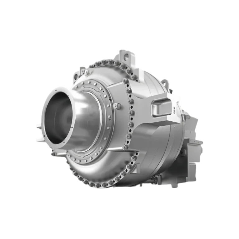
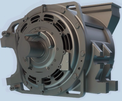
Overview of Transmission Gear box for Rail Car
Railway maintenance vehicles, construction vehicles and inspection vehicles are the main applications of track vehicles. The power output by the traction motor of the track vehicle is transmitted to the wheels through the gearbox, driving the track vehicle to move. Therefore, the gearbox is a key transmission component in the track vehicle. This article introduces the technical parameters of the two-stage transmission gearbox and the design and control of its key technologies. The design of the two-stage transmission gearbox was verified through type tests, which showed that it operates smoothly, has low noise, reliable sealing and good heat dissipation performance, meeting the expected design requirements.
| Track gauge | Motor rated speed | Wheel diameter | Motor starting torque | Shaft diameter | Motor maximum speed |
| 1435mm | 756r/min | 915mm | 4600Nm | 206mm | 4197r/min |
| Axle load | Total reduction ratio of the gearbox | Working environment temperature | Center distance between input and output | Motor rated power | Maximum operating speed of the vehicle |
| 23t | 4.14 | -25~45℃ | 502mm | 250kW | 160km/h |
1.Main technical parameters of the two-stage transmission gearbox:
The input end of the gearbox is connected to the motor shaft through a coupling. The power from the motor is transmitted to the axle through the first and second gear pairs of the gearbox. Since the axle and the driven gear of the second gear pair are fixedly connected, the axle is driven to rotate, driving the vehicle to move. The suspension method of the gearbox is as follows: The front end is connected to one end of the suspension rod through the lifting lugs set on the gearbox, and the other end of the suspension rod is connected to the crossbeam of the bogie. The suspension rod is flexibly connected to the gearbox and the crossbeam, which can alleviate the vibration and impact from the wheels and the bogie. The other end of the gearbox is supported on the axle through bearings.
2.Power transmission characteristics of the two-stage transmission gearbox
The input end of the gearbox is connected to the motor shaft through a coupling. The power from the motor is transmitted to the axle through the first and second gear pairs of the gearbox. Since the axle and the driven gear of the second gear pair are fixedly connected, the axle is driven to rotate, driving the vehicle to move. The suspension method of the gearbox is as follows: The front end is connected to one end of the suspension rod through the lifting lugs set on the gearbox, and the other end of the suspension rod is connected to the crossbeam of the bogie. The suspension rod is flexibly connected to the gearbox and the crossbeam, which can alleviate the vibration and impact from the wheels and the bogie. The other end of the gearbox is supported on the axle through bearings.
3. Design of key technologies of the two-stage transmission gearbox
3.1 Design of two-stage transmission gear pairs and gear system layout: Due to the limitation of installation space, the shape of the gearbox output end cannot be too large, which determines that the output gear cannot be too large. Therefore, the reduction ratios of the first and second stages cannot differ too much. Through the optimization of the gearbox shape, the first stage reduction ratio i1 is determined to be 2.037, and the second stage reduction ratio i2 is 2.032. To meet the requirements of high anti-scuffing ability, high contact strength and sufficient bending strength of the gears, the material of the gears is all high-toughness 18CrNiMo7-6 carburized steel, and carburizing and quenching are used for heat treatment. The content of carbides and retained austenite is strictly controlled, and the depth of the hardened layer and the transition layer are appropriately matched to control the microstructure. All gears are ground, and the gear accuracy reaches grade 6 or above. To further improve the transmission quality and reliability of the gears, reduce the dynamic load at the initial meshing, reduce the load deviation and reduce the noise, the tooth profile and tooth direction of the first and second-stage gears are modified bidirectionally.
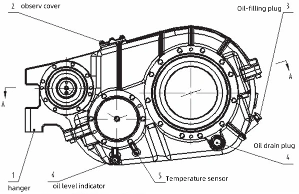
3.2 Design of the gearbox housing structure and strength verification: Considering the special assembly of the axle gearbox, the gearbox is divided into an upper housing and a lower housing along the plane connecting the middle shaft and the axle center. On both sides of the upper housing, there are oil collection grooves, and there are oil guide holes in the oil collection grooves leading to the bearing holes. An oil baffle is set in the upper part of the upper housing to direct the splashed oil to the oil collection grooves. In the bearing holes of the lower housing, there are oil baffles and oil return holes, and the inner cavity is separated into an oil stirring chamber and an oil storage chamber by the inner ribs. The bearing holes are provided with reinforcing ribs to strengthen the support of the bearings. The outer surface of the housing is provided with reinforcing ribs to increase the strength of the housing. At the same time, there are oil injection holes, oil discharge holes, oil level indicator holes, temperature sensor interfaces and observation holes on the outside.
4. Strength verification of the housing
The material of the gearbox is QT400-18, and the material parameters are shown in the table.
| Component | Material | Ensile Strength Sigma b/MPa | Yield Strength σs (sigma 0.2 )/MPa | Fatigue Strength Sigma – 1 /MPa | Extend Rate /% |
| gearbox | QT400-18 | 400 | 240 | 178 | 18 |